The induction motor, also known as asynchronous motor, is a type of AC electric motor. According to the different power phase, it can be divided into single-phase and three-phase. The main construction of the induction motor consists of two parts - stator and rotor. In addition, there are end bells, bearings, engine structure and other components. Below, more details on the main structure of the three-phase induction motor or the asynchronous motor will be provided.
construction of induction motors

1. Stator
The stator is a fixed part of the induction motor, consisting of an iron core, windings and motor structure.
Stator iron core
As part of the motor's magnetic circuit, it is installed inside the motor frame. It is a hollow cylinder, the outer wall of which is connected to the engine structure. And the stator windings are placed in the groove of the iron core inside. To reduce the loss of the iron core, the iron core of the stator is stacked with 0.5 mm thick silicon steel sheets.
Stator winding
It is a part of the electrical circuit of the motor, generating the rotating magnetic field by inducing three-phase alternating current. The stator windings are wound with insulated copper wires and embedded in the stator slot, which is separated by insulating material between the windings and the slot.
For the methods of connecting the stator windings of the three-phase induction motor, not all of them are connected to the star connection (connection Y). But only under the circumstance of high capacity and high voltage will they connect in this way. In general, as in the low-capacity, low-voltage induction motor, six ends of the three-phase stator winding wire are pulled to connect to the delta connection (Δ connection) or star connection (Y connection). In this way, the motor can be applied to two different levels of supply voltage, for example, the star connection is inserted into the 380V power supply and the delta connection used for the 220V power supply, which can satisfy the need of departure. In other words, it is designed as the delta connection for the 380V power supply and switched to the star connection at startup to achieve the reduced voltage starting objective. Wiring diagram of the three-phase induction motor stator winding
Motor frame
It fixes the stator core and windings and supports the rotor with two bells at the ends. In the meantime, it protects the electromagnet part of the entire engine and dissipates the heat generated during engine operation. The frame is usually made of iron or aluminium.

2. Rotor
The rotor is a rotating part of the induction motor, including iron core, windings and shaft etc.
Rotor iron core
It is also part of the magnetic circuit, usually stacked by silicone steels and fixed to the shaft.
Axis
It plays a role of torque conversion and supports the rotor. It is usually made of medium carbon steel or alloy steel.
Rotor winding
It produces induced current by cutting the magnetic field of the stator and, under the effect of the rotating magnetic field, forces the rotor to rotate. According to the different structure, it can be divided into two types: a squirrel cage rotor and rolled rotor.
The winding rotor windings can be connected to the star or delta connection. In general, the small capacity rotor is connected to the delta while the large and medium capacity rotor is connected to the star. These three ends of the winding wires are connected to three slip rings fixed to the shaft by an electric brush assembly. It can connect the external resistor to the rotor winding circuit. The purpose of rope resistance is to improve the characteristics of the motor or to adjust the speed of rotation.
The structure of the squirrel cage rotor winding is quite different from the structure of the stator. There are slots in the iron core of the rotor with a bar in each slot. Two ends of the iron core that connect all the bars to the external grooves, respectively, form a short circuit. If the iron core is removed from the stator, the shape of the winding is like a squirrel cage. Some bars are made of copper and others are aluminium. If the winding is made of copper, the prepared bare copper bar will be inserted into the crack in the iron core and then covered with copper rings at both ends, followed by welding; if the winding is made of aluminium, the molten aluminium liquid is directly melted into the slits of the iron core of the rotor, melted with rings and fan blades at the same time.
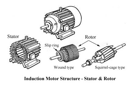
Image Source- Google


No comments:
Post a Comment
Thank you for reading.