Showing posts with label Alternator. Show all posts
Showing posts with label Alternator. Show all posts
Sunday, 19 July 2020
Why Alternator/Generator Rated in kVA. Not in kW?
As we definitely realize that why transformer evaluated in kVA rather than kW, the same reason here, for example, the power √3 VL IL Cos θ conveyed by the alternator and generator for a similar estimation of current, relies on p.f. (Power Factor=Cos θ) of the heap.
Be that as it may, the alternator conductors are determined for a distinct current and the protection at an attractive framework are intended for a clear voltage free of p.f. (Cos θ) of the heap. Consequently, clear power estimated in kVA is viewed as the evaluated intensity of the alternator.
Why Generator and Alternator evaluated in kVA. Not in kW?
The primary elements producers consider while planning electrical gadgets and apparatuses which give electric power like a transformer, UPS, alternators and generators, etc are burden and power factor. As they don't know precisely what is power factor and which sort of burden will be associated with the gadget and machines.
So they essentially plan and rate the electrical gadget as per its most extreme flow yield that the conduits can securely convey while they consider solidarity power factor (if there should be an occurrence of unadulterated resistive burden).
If we interface inductive or capacitive burden (When the power factor isn't at any rate solidarity), The yield would vary than as there are misfortunes happens because of low influence factor.
Consequently, KVA is a clear power which does not consider the PF (Power factor) rather than KW (Real Power).
Where:
KW= KVA X Cos θ
What's more, kVA = KW/Cos θ.
For instance,
If there should arise an occurrence of solidarity Power factor (1) for example unadulterated resistive burden. A 100kVA generator or alternator would give careful 100kW according to the accompanying equation.
P = V x I x Cos θ
kW = V x I x Cos θ
kW = 100 x 1 = 100 kW
On the off chance that we put the estimation of Cos θ as 1, The genuine power (kW) would be equivalent to the apparent control (kVA)
If there should arise an occurrence of inductive or capacitive burden, assume the power factor is 0.80.
Presently the genuine power would be
kW= KVA X Cos θ
kW = 100 X 0.80
kW= 80 kW.
Presently you now that why alternators, generators, transformer and UPS and so on are evaluated in kVA rather than kW.
EMF equation of an Alternator/AC Generator
EMF Equation of an Alternator/AC Generator
An alternator or AC generator (dynamo) is a gadget which converts mechanical Vitality to electrical vitality. When we supply the charging current by DC shunt generator through two slip rings (in ongoing alternators, they utilize electronic beginning framework rather than slip rings and commutators) because the field magnets are pivoting. remember that most alternators utilize a pivoting attractive field with a stationary armature.
At the point when the rotor turns, the stator conductors which are static in the event of alternator cut by attractive motion, they have instigated EMF delivered in them (as per Faraday's law of electromagnetic enlistment which expresses that if a conductor or loop joins with any evolving transition, there must be a prompted emf in it.
Note: We will examine the development, Working and Operation. Sorts of Alternators in subtleties in our next posts.EMF Equation of an Alternator and AC Generator
This incited EMF can be found by the EMF condition of the alternator which as pursues:
Lets,
P = No. of shafts
Z = No. of Conductors or Coil sides in arrangement/stage, for example, Z = 2T… Where T is the number of loops or turns per stage (Note that one turn or curl has two finishes or sides)
f = recurrence of actuated EMF in Hz
Φ = Flux per shaft (Weber)
N = rotor speed (RPM)
Kd= Distribution factor = Kd= Distribution factor for emf condition of alternator and air conditioning generator
Where Distribution factor = Kd =distribution factor
Kc or KP = Cos α/2
Whenever initiated EMF is accepted sinusoidal at that point,
Kf = Form factor = 1.11
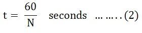
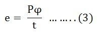
In one upheaval of the rotor for example in 60/N seconds, every conductor is cut by a transition of ΦP Webers.
dφ = ΦP and furthermore dφ = 60/N seconds
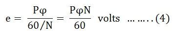
at that point incited e.m.f per conductor ( normal) = EMF EQUATION OF AN ALTERNATOR OR AC GENERATOR… .. (I)
In any case, we realize that:
f = PN/120 or N= 120f/P
Putting the estimation of N in Equation (I), we get,
Normal estimation of EMF per conductor = EMF EQUATION OF AN ALTERNATOR∴ (N= 120f/P)
On the off chance that there are Z conductors in arrangement per stage,
at that point normal e.m.f per stage = 2 f Φ Z Volts = 4 f ΦT Volts … .. (Z=2T)
Likewise, we realize that;
Structure Factor= RMS Value/Average Value
= RMS value= Form factor x Average Value,
= 1.11 x 4fΦT = 4.44fΦT Volts.
(Note that is the very same condition as the EMF condition of the transformer)
What's more, the real accessible voltage per stage
= 4 Kc Kd f ΦT = 4 Kf Kc Kd f ΦT Volts.
Note: If alternator or AC generator is star associated as ordinarily the case, at that point the Line Voltage is √3 times the stage voltage as got from the above recipe
An alternator or AC generator (dynamo) is a gadget which converts mechanical Vitality to electrical vitality. When we supply the charging current by DC shunt generator through two slip rings (in ongoing alternators, they utilize electronic beginning framework rather than slip rings and commutators) because the field magnets are pivoting. remember that most alternators utilize a pivoting attractive field with a stationary armature.
At the point when the rotor turns, the stator conductors which are static in the event of alternator cut by attractive motion, they have instigated EMF delivered in them (as per Faraday's law of electromagnetic enlistment which expresses that if a conductor or loop joins with any evolving transition, there must be a prompted emf in it.
Note: We will examine the development, Working and Operation. Sorts of Alternators in subtleties in our next posts.EMF Equation of an Alternator and AC Generator
This incited EMF can be found by the EMF condition of the alternator which as pursues:
Lets,
P = No. of shafts
Z = No. of Conductors or Coil sides in arrangement/stage, for example, Z = 2T… Where T is the number of loops or turns per stage (Note that one turn or curl has two finishes or sides)
f = recurrence of actuated EMF in Hz
Φ = Flux per shaft (Weber)
N = rotor speed (RPM)
Kd= Distribution factor = Kd= Distribution factor for emf condition of alternator and air conditioning generator
Where Distribution factor = Kd =distribution factor
Kc or KP = Cos α/2
Whenever initiated EMF is accepted sinusoidal at that point,
Kf = Form factor = 1.11
In one upheaval of the rotor for example in 60/N seconds, every conductor is cut by a transition of ΦP Webers.
dφ = ΦP and furthermore dφ = 60/N seconds
at that point incited e.m.f per conductor ( normal) = EMF EQUATION OF AN ALTERNATOR OR AC GENERATOR… .. (I)
In any case, we realize that:
f = PN/120 or N= 120f/P
Putting the estimation of N in Equation (I), we get,
Normal estimation of EMF per conductor = EMF EQUATION OF AN ALTERNATOR∴ (N= 120f/P)
On the off chance that there are Z conductors in arrangement per stage,
at that point normal e.m.f per stage = 2 f Φ Z Volts = 4 f ΦT Volts … .. (Z=2T)
Likewise, we realize that;
Structure Factor= RMS Value/Average Value
= RMS value= Form factor x Average Value,
= 1.11 x 4fΦT = 4.44fΦT Volts.
(Note that is the very same condition as the EMF condition of the transformer)
What's more, the real accessible voltage per stage
= 4 Kc Kd f ΦT = 4 Kf Kc Kd f ΦT Volts.
Note: If alternator or AC generator is star associated as ordinarily the case, at that point the Line Voltage is √3 times the stage voltage as got from the above recipe
Winding Terminologies in an alternator

- Conductor: The part of the wire, which is under the influence of the magnetic field and responsible for the induced emf is called the active length of the conductor. The conductors are placed in the armature slots.
- Turn: A conductor in one slot, when connected to a conductor in another slot forms a turn. So Two conductors constitute a turn.
- Coil: As there is the number of turns, for simplicity the number of turns are grouped together to form a coil. Such a coil is called a multi-turn coil. A coil may consist of a single turn called a single turn coil.
- Coil Side: Coil consists of many turns. Part of the coil in each slot is called coil side of a coil.
- Pole pitch: It is centre to centre distance between the two adjacent poles. We have seen that for one rotation of the conductors, 2 poles are responsible for 360o. electrical of emf, 4 poles are responsible for 720o. electrical of emf and so on. So 1 pole is responsible for 180o. electrical is also called one pole pitch. Practically how many slots are under one pole which is responsible for 180o.electrical, are measured to specify the pole pitch.
e.g. consider 2 poles, 18 slots armature of an alternator. Then under 1 pole, there are 18/2 i.e. 9 slots. so pole pitch is 9 slots or 180 degrees electrical. This means 9 slots are responsible to produce a phase difference of 180 degrees between the EMFs induced in different conductors.
This number is slots/pole is denoted as 'n'
Pole pitch = 180 degree electrical
= slots per pole (number of slots/P)=n
6. Slot Angle (β): The phase difference contributed by one slot in degrees electrical is called slot angle β.
As slots per pole contribute 180-degree electrical which is denoted as 'n', we can write,
So, 1 Slot angle= 180 degree/n
means
β=180 degree/n
In the above example,
n= 18/2 =9, while β=180 degree/n = 20 degree
Note:- This means that if we consider an induced emf in the conductors which are placed in the slots which are adjacent to each other, there will exist a phase difference of β degree in between them. While if emf induced in the conductors which are placed in slots which are 'n' slots distance away, there will exist a phase difference of 180 degrees in between them.

Types of Armature winding of an AC machine
In general armature winding is classified as,


- Single-layer and double-layer winding
- Full pitch and short pitch winding
- Concentrated and distributed winding
1. Single-layer and Double-layer winding- If a slot consists of only one coil side, the winding is said to be a single layer. This is shown in figure-

While there are two coil sides per slot, one at the bottom and one at the top the winding is called Double-layer winding.
A lot of space gets wasted in single layer hence in practice generally double layer winding is preferred.
2. Full pitch and short pitch winding- As seen earlier, one pole pitch is 180 degrees electrical. the value of 'n', slots per pole indicates how many slots are contributing 180-degree electrical phase difference. So if coil side in one slot is connected to a coil side in another slot which is one pole pitch distance away from the first slot, the winding is said to be full pitch winding and coil is called full pitch coil.
For example in 2 poles, 18 slots alternator, the pole pitch is n= 18/2 =9 slots. So if coil side in slot No. 1 is connected to coil side in slot No. 10 such that two slots No. 1 and No. 10 are one pole pitch or n slots or 180 degrees electrical apart, the coil is called full pitch coil.
Here we can define one more term related to a coil called coil span.
3. Coil Span- It is the distance on the periphery of the armature between two coil sides of a coil. it is usually expressed in terms of the number of slots or degrees electrical. So if the coil span is 'n' slots or 180 degrees electrical the coil is called full pitch coil. This is shown in figure-

As against this if coils are used in such a way that coil span is slightly less than a pole pitch i.e. less than 180-degree electrical, the coils are called, Short pitched coils or fractional pitched coils.
So in 18 slots, 2 pole alternator instead of connecting a coil side in slot No. 1 to slot No. 10, it is connected to a coil side in slot No. 9 or slot No. 8, the coil is said to be short pitched coil and winding is called short pitch winding. This is shown in figure-
Advantages of Short Pitch Coils-
In actual practice, short pitch coils are used as it has the following advantages:
- The length required for the end connections of coils is less i.e. inactive length of winding is less. so less copper is required. Hence economical.
- Short pitching eliminates high-frequency harmonics which distort the sinusoidal nature of emf Hence waveform of an induced emf is more sinusoidal due to short pitching.
- As high-frequency harmonics get eliminated, eddy current and hysteresis losses which depend on frequency also get minimized. This increases efficiency.
To be continued.....
Integral slot winding & fractional slot winding of AC machine
1. Integral slot winding-The value of slots per pole per phase decides the class of the winding.
m= Slots/Pole/Phase
Note- When the value of m is an integer, then the winding is called integral slot winding.
Consider 2 pole, 12 slots alternator hence,
n= Slots/Pole =12/2 =6
Pole pitch= 180 degree = 6 slots
m= n/2 = 6//2 =3
As m is an integer, the type of winding is integral slot winding. This winding can be full pitch winding or short pitch winding.
Let, the winding is full pitch winding. For integral slot winding, coils of one coil group lying under one pole pair are connected in series. Thus the end of the first coil is connected to start of the next coil lying to the right of the first coil. The alternate coil groups must be reverse connected such that emf induced in them is addictive in nature. Any slot contains the coil sides which belong to the same phase. Such a winding is shown in figure-

If the short pitch coils are used for integral slot winding then in each group of the slots per pole phase, the coil sides of different phases exist.
2. fractional slot winding- This is another class of winding which depends on the value of m.
Note- The winding in which slots per pole per phase (m) is a fractional number is called fractional slot winding.
In such a winding, the number of slots (S) must be divisible by 3. Thus slots per phase is an integer which is necessary to obtain symmetrical three-phase winding. But slots per pole (n) and slots per pole per phase (m) both are fractional. As n is a fraction, the coils cannot be the full pitch. Thus if there are 54 slots and 8 poles then the slots per pole n= 54/8 =6.75 hence coil span can be 7 or 6. Generally, short pitch coils are used. Such a fractional slot winding can be easily achieved with double layer winding.
In a balanced three-phase winding, a basic unit under a pole pair (N and S) is repeated for remaining pole pairs where m is an integer. In fractional slot winding, they are reduced to an irreducible fraction by taking out the highest common factor in the number of slots and poles.
Let S= Number of Slots
P= Number of Poles
then for a 3 phase winding,
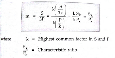

The number k indicates the number of repeatable units and the number of possible parallel paths. The characteristics ratio indicates that there are Sk coils per phase distributed among Pk poles.
Thus the winding is to be considered only of Pk poles out of P poles and for other poles it is repeated.
Similarly, the winding arrangement is to be considered for Sk slots out of total S slots and for other slots it is repeated.
In a double layer winding, only the arrangement of the top layer is to be considered. This gets repeated in the bottom layer in which the corresponding coil sides are located one coil span away.
Advantages of Fractional slot winding-
The various advantages of fractional slot winding are-
- Though appear to be complicated, easy to manufacture.
- The number of armature slots (S) need not be an integral multiple of the number of poles (P)
- The number of slots can be selected for which notching gear is available, which is economical
- There is saving in machine tools.
- High-frequency harmonics are considerably reduced.
- The voltage waveform available is sinusoidal in nature.
Friday, 17 July 2020
Phasor Diagram Of Synchronous Generator
In this article, we will discuss one of the easiest methods of making the phasor diagram for a synchronous generator. Now, let's write the various notes for each quantity in a single location, this will help us understand the phasor diagram more clearly. In this phasor diagram, we will use:
Ef, which indicates excitation voltage
Vt indicating terminal voltage
Ia that denotes the chain of the armature
θ that denotes the phase angle between Vt and Ia
ᴪ that denotes the angle between Ef and Ia
δ that denotes the angle between Ef and Vt
which indicates the strength of the reinforcement per phase
To draw the phasor diagram, we will use Vt as a reference. Consider these two important points that are written below:
These two points are necessary to make the phasor diagram of the synchronous generator. Given below is the phasor diagram of the synchronous generator:
In this phasor diagram, we trace the direction of Ia in phase with that of Ef, as per point 1 mentioned above. Now we are going to derive an expression for the emf excitation in each case. We have three cases written below:
The following are the phasor diagrams for all operations.
Ef, which indicates excitation voltage
Vt indicating terminal voltage
Ia that denotes the chain of the armature
θ that denotes the phase angle between Vt and Ia
ᴪ that denotes the angle between Ef and Ia
δ that denotes the angle between Ef and Vt
which indicates the strength of the reinforcement per phase
To draw the phasor diagram, we will use Vt as a reference. Consider these two important points that are written below:
- We already know that if a machine is working as a synchronous generator, the direction of Ia will be in phase with that of Ef.
- Phasor Ef is always ahead of Vt.
These two points are necessary to make the phasor diagram of the synchronous generator. Given below is the phasor diagram of the synchronous generator:
In this phasor diagram, we trace the direction of Ia in phase with that of Ef, as per point 1 mentioned above. Now we are going to derive an expression for the emf excitation in each case. We have three cases written below:
- Generating operation with delayed power factor.
- Generation operation on the unit's power factor.
- Generation operation on the main power factor.
The following are the phasor diagrams for all operations.
 |
| Image Source- Google |
Armature reaction in the alternator or synchronous generator
Every rotating electrical machine works based on Faraday's law. Every electrical machine requires a magnetic field and a coil (known as armature) with relative movement between them. In the case of an alternator, we supply electricity to the pole to produce a magnetic field and the output energy is removed from the armature. Due to the relative movement between the field and the armature, the armature conductor cuts off the flow of the magnetic field and, therefore, there would be changes in the flow connection with these armature conductors. According to Faraday's law of electromagnetic induction, there would be an induced emf in the armature. Thus, as soon as the load is connected to the armature terminals, there is a current flowing in the armature coil.
As soon as the current begins to flow through the armature conductor, there is a reverse effect of this current on the flow of the alternator's main field (or synchronous generator). This reverse effect is called an armature reaction in the alternator or synchronous generator. In other words, the effect of the armature flow (stator) on the flow produced by the poles in the rotor field is called the armature reaction.
We already know that a current conductor produces its own magnetic field, and that magnetic field affects the alternator's main magnetic field.
It has two undesirable effects: it distorts the main field or reduces the flow of the main field or both. They deteriorate the performance of the machine. When the field is distorted, it is known as a cross magnetization effect. And when the field flow is reduced, it is known as a demagnetizing effect.
The conversion of electromechanical energy takes place through the magnetic field as a medium. Due to the relative movement between the armature conductors and the main field, an emf is induced in the armature windings whose magnitude depends on the relative speed and magnetic flux. Due to the reaction of the armature, the flow is reduced or distorted, the induced net fraction is also affected and, therefore, the performance of the machine decreases.
Alternator armature reaction
In an alternator like all other synchronous machines, the effect of the armature reaction depends on the power factor, that is, the phase relationship between the terminal voltage and the armature current.
Reactive power (delay) is the energy of the magnetic field; therefore, if the generator supplies a delayed load, it implies that it is supplying the load with magnetic energy. As this energy comes from the excitation of the synchronous machine, the net reactive energy is reduced in the generator.
Therefore, the reaction of the armature is demagnetizing. Likewise, the armature reaction has a magnetizing effect when the generator supplies an initial charge (as the main charge carries the main VAR) and, in return, supplies delayed VAR (magnetic energy) to the generator. In the case of a purely resistive load, the armature reaction is only cross-magnetized.
The reaction of the alternator armature or synchronous generator depends on the phase angle between the stator armature current and the voltage induced in the alternator armature winding.
The phase difference between these two quantities, that is, current and voltage of the armature, can vary from - 90o to + 90o
If that angle is θ, then

To understand the real effect of this angle on the alternator armature reaction, we’ll consider three standard cases,
When θ = 0
When θ = 90o
When θ = - 90o
The reaction of alternator armature in unit power factor
In the power factor of the unit, the angle between the armature current I and the induced emf E is zero. This means that the armature current and the induced emf are in the same phase. But we know theoretically that the EMF induced in the armature is due to the change in the flow of the main field, connected to the armature conductor.
As the field is excited by DC, the main flow of the field is constant with the field magnets, but it would be alternated with the armature, as there is a relative movement between the field and the armature in the alternator. If the flow of the alternator's main field with the armature can be represented as

Then the induced emf through the armature is proportional to dɸf / dt.

Therefore, from these equations (1) and (2) above, it is clear that the angle between, φf and the induced emf will be 90o.
Now, the armature flow φa is proportional to the armature current I. Therefore, the armature flow is in phase with the armature current I.
Again, in the unit, the electric power factors I and E are in the same phase. Therefore, in the power factor of the unit, is in phase with E. Therefore, in this condition, the armature flow is in phase with the induced EMF and the field flow is in quadrature with E. Therefore, the armature flow φa is square to the main field flow φf.
As these two flows are perpendicular to each other, the reaction of the alternator armature in the power factor of the unit is of the type of distortion or cross magnetization.
As the armature flow pushes the main field flow perpendicularly, the main field flow distribution under one face of the pole does not remain uniformly distributed. The density of the flow under the tips of the poles on the right increases slightly, while under the tips of the poles in front it decreases.
Alternator armature reaction in delayed zero power factor
At the zero delay power factor, the armature current is 90o for the emulsion induced in the armature.
Like the emf induced in the armature coil due to the main field flow, the emf takes the main field flow by 90o. From equation (1) we obtain the field flow,

Therefore, at ωt = 0, E is maximum and φf is zero.
At ωt = 90o, E is zero and φf has the maximum value.
At ωt = 180o, E is maximum and φf zero.
At ωt = 270o, E is zero and φf has a maximum negative value.
Here, got the maximum value 90 ° before E. Therefore leads E by 90 °.
Now, the armature current I is proportional to the armature flow φa and I is E at 90o. Therefore, is E at 90o.
Thus, it can be concluded that the flux of field flow takes E at 90o.
Therefore, the armature flow and the field flow act directly opposite to each other. Thus, the alternator armature reaction in the zero delay power factor is a purely demagnetizing type. This means that the flow of the armature directly weakens the flow of the main field.
The reaction of alternator armature in the main power factor
In the condition of the main power factor, the armature current "I" induces the fem E by an angle of 90o. Again, we show only the derived leads field flow, induced by EME by 90o.
Again, the armature flow φa is proportional to the armature current I. Therefore, φa is in phase with I. Therefore, the armature flow φa also takes E, at 90o, as I conduct E, at 90o.
As in this case, both the flux of the armature and the lead of the flux of the field, induced by the fem E by 90o, it can be said that the flux of the field and the flux of the armature are in the same direction. Therefore, the resulting flow is simply the arithmetic sum of the field flow and the armature flow. Therefore, finally, it can be said that the alternator armature reaction due to a purely main electrical power factor is the type of magnetization.
As soon as the current begins to flow through the armature conductor, there is a reverse effect of this current on the flow of the alternator's main field (or synchronous generator). This reverse effect is called an armature reaction in the alternator or synchronous generator. In other words, the effect of the armature flow (stator) on the flow produced by the poles in the rotor field is called the armature reaction.
We already know that a current conductor produces its own magnetic field, and that magnetic field affects the alternator's main magnetic field.
It has two undesirable effects: it distorts the main field or reduces the flow of the main field or both. They deteriorate the performance of the machine. When the field is distorted, it is known as a cross magnetization effect. And when the field flow is reduced, it is known as a demagnetizing effect.
The conversion of electromechanical energy takes place through the magnetic field as a medium. Due to the relative movement between the armature conductors and the main field, an emf is induced in the armature windings whose magnitude depends on the relative speed and magnetic flux. Due to the reaction of the armature, the flow is reduced or distorted, the induced net fraction is also affected and, therefore, the performance of the machine decreases.
Alternator armature reaction
In an alternator like all other synchronous machines, the effect of the armature reaction depends on the power factor, that is, the phase relationship between the terminal voltage and the armature current.
Reactive power (delay) is the energy of the magnetic field; therefore, if the generator supplies a delayed load, it implies that it is supplying the load with magnetic energy. As this energy comes from the excitation of the synchronous machine, the net reactive energy is reduced in the generator.
Therefore, the reaction of the armature is demagnetizing. Likewise, the armature reaction has a magnetizing effect when the generator supplies an initial charge (as the main charge carries the main VAR) and, in return, supplies delayed VAR (magnetic energy) to the generator. In the case of a purely resistive load, the armature reaction is only cross-magnetized.
The reaction of the alternator armature or synchronous generator depends on the phase angle between the stator armature current and the voltage induced in the alternator armature winding.
The phase difference between these two quantities, that is, current and voltage of the armature, can vary from - 90o to + 90o
If that angle is θ, then
To understand the real effect of this angle on the alternator armature reaction, we’ll consider three standard cases,
When θ = 0
When θ = 90o
When θ = - 90o
The reaction of alternator armature in unit power factor
In the power factor of the unit, the angle between the armature current I and the induced emf E is zero. This means that the armature current and the induced emf are in the same phase. But we know theoretically that the EMF induced in the armature is due to the change in the flow of the main field, connected to the armature conductor.
As the field is excited by DC, the main flow of the field is constant with the field magnets, but it would be alternated with the armature, as there is a relative movement between the field and the armature in the alternator. If the flow of the alternator's main field with the armature can be represented as
Then the induced emf through the armature is proportional to dɸf / dt.
Therefore, from these equations (1) and (2) above, it is clear that the angle between, φf and the induced emf will be 90o.
Now, the armature flow φa is proportional to the armature current I. Therefore, the armature flow is in phase with the armature current I.
Again, in the unit, the electric power factors I and E are in the same phase. Therefore, in the power factor of the unit, is in phase with E. Therefore, in this condition, the armature flow is in phase with the induced EMF and the field flow is in quadrature with E. Therefore, the armature flow φa is square to the main field flow φf.
As these two flows are perpendicular to each other, the reaction of the alternator armature in the power factor of the unit is of the type of distortion or cross magnetization.
As the armature flow pushes the main field flow perpendicularly, the main field flow distribution under one face of the pole does not remain uniformly distributed. The density of the flow under the tips of the poles on the right increases slightly, while under the tips of the poles in front it decreases.
Alternator armature reaction in delayed zero power factor
At the zero delay power factor, the armature current is 90o for the emulsion induced in the armature.
Like the emf induced in the armature coil due to the main field flow, the emf takes the main field flow by 90o. From equation (1) we obtain the field flow,
Therefore, at ωt = 0, E is maximum and φf is zero.
At ωt = 90o, E is zero and φf has the maximum value.
At ωt = 180o, E is maximum and φf zero.
At ωt = 270o, E is zero and φf has a maximum negative value.
Here, got the maximum value 90 ° before E. Therefore leads E by 90 °.
Now, the armature current I is proportional to the armature flow φa and I is E at 90o. Therefore, is E at 90o.
Thus, it can be concluded that the flux of field flow takes E at 90o.
Therefore, the armature flow and the field flow act directly opposite to each other. Thus, the alternator armature reaction in the zero delay power factor is a purely demagnetizing type. This means that the flow of the armature directly weakens the flow of the main field.
The reaction of alternator armature in the main power factor
In the condition of the main power factor, the armature current "I" induces the fem E by an angle of 90o. Again, we show only the derived leads field flow, induced by EME by 90o.
Again, the armature flow φa is proportional to the armature current I. Therefore, φa is in phase with I. Therefore, the armature flow φa also takes E, at 90o, as I conduct E, at 90o.
As in this case, both the flux of the armature and the lead of the flux of the field, induced by the fem E by 90o, it can be said that the flux of the field and the flux of the armature are in the same direction. Therefore, the resulting flow is simply the arithmetic sum of the field flow and the armature flow. Therefore, finally, it can be said that the alternator armature reaction due to a purely main electrical power factor is the type of magnetization.
Nature of the armature reaction
- The reaction flow of the armature is constant in magnitude and rotates at synchronous speed.
- The armature reaction is cross-magnetized when the generator provides a load on the unit's power factor.
- When the generator provides a load on the main power factor, the armature reaction is partially demagnetized and partially crossed magnetized.
- When the generator provides a load on the main power factor, the armature reaction is partially magnetized and partially crossed magnetized.
- The armature flow acts independently of the main field flow.
Image Source- Google
Parallel operation of synchronous generator
The Alternator is really an AC generator. In the alternator, an EMF is induced in the stator (fixed wire) by the effect of the rotating magnetic field (rotor) due to Faraday's law of induction. Due to the modern rotational speed of the field poles, it is also known as the modern generator.
Here, we can discuss the parallel operation of the synchronous generator. When AC systems are interconnected for efficiency, the alternators must also be connected in parallel. There will be more than two synchronous generators connected in parallel to the production stations.
The conditions that must be met are
1. The phase sequence of the input motor voltage and the busbar voltage must be the same.
2. The RMS (terminal voltage) line voltage of the busbar or the current machine and the incoming machine must be the same.
3. The phase angle of the two systems must be equal.
4. The frequency of the two terminals (input motor and busbar) must be almost the same. Large transient currents will occur when the frequencies are not nearly the same.
Departure from the above conditions will result in the formation of surges and current. It also leads to unwanted electromechanical oscillation of the rotor which leads to equipment damage.
Here, we can discuss the parallel operation of the synchronous generator. When AC systems are interconnected for efficiency, the alternators must also be connected in parallel. There will be more than two synchronous generators connected in parallel to the production stations.
Condition for parallel application of the synchronous generator
Search for comments that I need to complete for parallel use of the converter. Before applying, you should look for the additional information required as.- The method of providing screen access, display and zoom and infinite channel line beauty is also known as synchronization.
- Running machines are the machine that changes the load.
- The incoming machine is the exchanger or machine that you need to list delivery with the system.
The conditions that must be met are
1. The phase sequence of the input motor voltage and the busbar voltage must be the same.
2. The RMS (terminal voltage) line voltage of the busbar or the current machine and the incoming machine must be the same.
3. The phase angle of the two systems must be equal.
4. The frequency of the two terminals (input motor and busbar) must be almost the same. Large transient currents will occur when the frequencies are not nearly the same.
Departure from the above conditions will result in the formation of surges and current. It also leads to unwanted electromechanical oscillation of the rotor which leads to equipment damage.
General procedure for parallel synchronous generator
The following figure shows an alternator (generator 2) paralleling a power system (generator 1). These two machines are to be synchronized to supply power to a load. Generator 2 is almost parallel with the help of a switch, S1. This switch must never be closed without fulfilling the above conditions. |
| Image Source- Google |
- To be equal to the voltages of the terminals. This can be done by adjusting the voltage at the input machine terminal by changing the field current and making it equal to the operating system line voltage using voltmeters.
- There are two methods for controlling the phase sequence of machines. They are as follows
- The first uses a Synchroscope. It does not actually control the phase sequence but is used to measure the difference in phase angles.
- The second method is the three lamp method (Figure 2). Here we can see three lamps connected to the switch terminals, S1. The lamps are bright if the phase difference is large. The lamps dim if the phase difference is small. The lamps will appear dim and bright together if the phase sequence is the same. The lamps will be bright in progress if the phase sequence is opposite. This sequence of phases can be matched by changing the connections in two phases on one of the generators.
 |
| Image Source- Google |
3. Next, we have to check and verify the frequency of the system received and running. It must be almost the same. This can be done by inspecting the frequency of dimming and brightness of the lamps.
4. When the frequencies are almost equal, the two voltages (input alternator and operating system) change the phase gradually. These changes can be observed and switch S1 can be closed when the phase angles are equal.
Advantages of parallel synchronous generator
- When maintenance or inspection occurs, one machine can be taken out of service and the other alternators can maintain continuity of supply.
- The cargo supply can be increased.
- During light loads, more than one alternator can be switched off while the other operates at an almost full charge.
- High efficiency.
- The operating cost is reduced.
- It guarantees the protection of the supply and allows an economical generation.
- The generation cost is reduced.
- The failure of a generator does not cause any interruption in the supply.
- The reliability of the entire power system increases.
Tuesday, 4 February 2020
EMF equation of DC generator
As the armature turns, a voltage is created in its loops. On account of a generator, the emf of the pivot is known as the Generated emf or Armature emf and is indicated as Er = Eg. On account of an engine, the emf of the pivot is known as Back emf or Counter emf and spoke to as Er = Eb. The articulation for emf is same for both the tasks. I.e., for Generator just as for Motor.
Derivation of EMF Equation of a DC Machine – Generator and Motor
Let,
- P – Number of poles of the machine
- ϕ – Flux per pole in Weber.
- Z – Total number of armature conductors.
- N – Speed of armature in revolution per minute (r.p.m).
- A – number of parallel paths in the armature winding.
In one revolution of the armature, the flux cut by one conductor is given as
Time taken to complete one revolution is given as
Therefore, the average induced e.m.f in one conductor will be
Putting the value of (t) from Equation (2) in the equation (3) we will get
The number of conductors connected in series in each parallel path = Z/A.
Therefore, the average induced e.m.f across each parallel path or the armature terminals is given by the equation shown below.
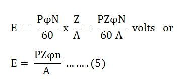
Where n is the speed in revolution per second (r.p.s) and given as

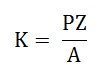
For a given machine, the number of poles and the number of conductors per parallel path (Z/A) are constant. Hence, equation (5) can be written as
Where, K is a constant and given as
Therefore, the average induced emf equation can also be written as
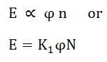
Where K1 is another constant and hence induced emf equation can be written as
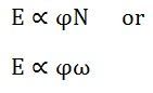
Where ω is the angular velocity in radians/second is represented as
Along these lines, plainly the instigated emf is straightforwardly relative to the speed and motion per shaft. The extremity of instigated emf relies on the bearing of the attractive field and the heading of revolution. If both of the two is turn around the extremity changes, however, if two are switched the extremity stays unaltered.
This initiated emf is an essential wonder for all the DC Machines whether they are filling in as a generator or engine.
If the machine DC Machine is filling in as a Generator, the instigated emf is given by the condition demonstrated as follows.
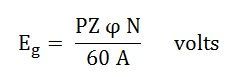
Where Eg is the Generated Emf
If the machine DC Machine is working as a Motor, the induced emf is given by the equation shown below.
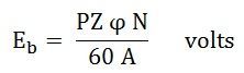
In a motor, the induced emf is called Back Emf (Eb) because it acts opposite to the supply voltage.
Wednesday, 5 December 2018
Synchronous Speed
It is clear that for the fixed number of poles, the alternator has to be rotated at a particular speed to keep the frequency of the generated emf constant at the required value. Such a speed is called Synchronous Speed of the alternator denoted as Ns.
So Ns=120f⁄P
Where f= Required Frequency
In our nation, the frequency of an alternating emf is standard equal to 50 Hz. to get 50 Hz frequency, for the different number of poles, the alternator must be driven at different speeds called Synchronous Speeds. Following table gives the values of the synchronous speeds for the alternators having a different number of poles.

From the table, it can be seen that the minimum number of poles for an alternator can be two hence maximum value of synchronous speed possible in our nation i.e. for the frequency of 50 Hz is 3000 rpm.
Sunday, 2 December 2018
Frequency of induced emf in an alternator

I hope that this article will be informative for you all.
Thanks and Regards
Er. Abhishek Srivastava
Mechanical and Electrical Angle
We have seen that for 2 pole alternator, one mechanical revolution corresponding to one electrical cycle of an induced emf Now consider 4 pole alternator i.e. the field winding is designed to produce 4 poles. Due to 4 poles, the magnetic axis exists diagonally as shown in figure-

Now in position 1 of the conductor, the velocity component is parallel to the flux lines while in position 2, there is the gathering of flux lines and entire velocity component is perpendicular to the flux lines.
figure-

So at position 1, the induced emf in the conductor is zero while at position 2, it is maximum. Similarly, as conductor rotates, the induced emf will be maximum at positions 4, 6 and 8 and will be minimum at positions 3, 5 and 7. So during one complete revolution of the conductor, inducted emf will experience four times maxima, twice in either direction and four times zero. This is because of the distribution of flux lines due to the existence of four poles.
So if we plot the nature of the induced emf, for one revolution of the conductor, we get the two electrical cycles of the induced emf, as shown in figure-

So for a four-pole alternator, we can write,
3600 electrical = 7200 mechanical
From this, we can establish the general relation between degrees mechanical and degrees electrical as.3600 electrical = 3600 x P/2 mechanical
P= No. of Poles
i.e.
10 electrical = (P/2)0 mechanical
I hope that this article will be informative for you all.
Thanks and Regards
Er. Abhishek Srivastava
Working Principle of an Alternator
The Alternator works on the principle of Electromagnetic induction. When there is a relative motion between the conductors and the flux, emf gets induced in the conductors. The dc generators also work on the same principle. The only difference in the practical alternator and a dc generator is that in an alternator the conductors are stationary and field is rotating. But for the understanding purpose, we can always consider the relative motion of conductors concerning the flux produced by the field winding.
Consider a relative motion of a single conductor under the magnetic field produced by two stationary poles. The magnetic axis of the two poles produced by field is vertical, shown by dotted lines.
Let the conductor starts rotating from Position 1. At this instant, the entire velocity component is parallel to the flux lines. Hence there is no cutting of flux lines by the conductor. So d∅/dt at this instant is zero and hence induced emf in the conductor is also zero.

As the conductor moves from position 1 towards position 2, the art of the velocity component becomes perpendicular to the flux lines and proportional to that, emf gets induced in the conductor. The magnitude of such an induced emf increases as the conductor moves from position 1 towards 2.
At position 2, the entire velocity component is perpendicular to the flux lines. Hence there exists maximum cutting of the flux lines. And at this instant, the induced emf in the conductor is at its maximum.
As the position of conductor changes from 2 towards 3, The velocity component perpendicular to the flux starts decreasing and hence induced emf magnitude also starts decreasing. At position 3, again the entire velocity component is parallel to the flux lines and hence at this instant induced emf in the conductor is zero.
As the conductor moves from position 3 towards 4, the velocity component perpendicular to the flux lines again starts increasing. But the direction of the velocity component now is opposite to the direction of velocity component existing during the movement of the conductor from position 1 to 2. Hence and induced emf in the conductor increases but in the opposite direction.

At position 4, it achieves maxima in the opposite direction, as the entire velocity component becomes perpendicular to the flux lines.
Again from position 4 to 1, induced emf decreases and finally at position 1, again becomes zero. This cycle continues as conductor rotates at a certain speed.
So if we plot the magnitudes of the induced emf against the time, we get an alternating nature of the induced emf as shown in the figure.
This is the working principle of an alternator.
I hope that this article will be informative for you all.
Thanks and Regards
Er. Abhishek Srivastava
Saturday, 1 December 2018
Methods of ventilation in an Alternator
- Natural Ventilation- A fan is attached to either end of the machine. The ventilating medium is nothing but an atmospheric air which is forced over the machine parts, carrying away the heat. This circulation is possible with or without ventilating ducts. The ventilating ducts if provided may be either axial or radial.
- Closed Circuit Ventilating System- An atmospheric air may contain injurious elements like dust, moisture, acidic fumes etc. which are harmful for the insulation of the winding. Hence for large capacity machines, closed-circuit system is preferred for ventilation. The ventilating medium used is generally Hydrogen. The hydrogen circulated over the machine parts is cooled with the help of water-cooled heat exchangers. Hydrogen provides very effective cooling than air which increases the rating of the machine up to 30 to 40 % for the same size. All modern alternators use closed-circuit ventilation with the help of hydrogen as a ventilating medium.
I hope that this article will be informative for you all.
Thanks and Regards
Er. Abhishek Srivastava
Excitation Systems of an Alternator
The synchronous machines whether alternator or motor are necessarily separately exciting machines. Such machines always require the flux for the operation which is provided by the field winding. Giving dc supply to the field winding, for the production of the necessary flux is called excitation.
For the small machines, the required dc supply is obtained from a dc generator called exciter. It is mounted on the main shaft of the alternator. The dc output of the exciter is given to the field winding of the alternator through slip ring and brush assembly as generally, the field winding is on the rotor. In some machines, a current is supplied to the exciter by another dc generator called pilot exciter. But this arrangement is not very sensitive, quick and effective if it is required to change the excitation of the alternator.
For the medium size machines instead of dc generators, ac generators are used called ac exciters. The output of such ac exciters is rectified and then given to the rotor of the main alternator using slip ring and brush assembly. The excitation can be varied and controlled as per requirement in such a method.
Still, these two methods are not very much suitable for the large alternators hence a brush-less excitation system is used for the large alternators.
Brush-less Excitation System
With the increase in rating of an alternator, the supply of necessary magnetic field becomes difficult as the current values may reach up to 4000 A. If we use conventional excitation systems such as a dc generator whose output is supplied to the alternator field through brushes and slip rings then problem invariably associated with slip rings commutators and brushes regarding cooling and maintenance. Thus modern excitation systems are developed which minimizes these problems by avoiding the use of brushes. Such excitation system is called Brush-less excitation system which is shown in figure-
 It consists of silicon diode rectifiers which are mounted on the same shaft of the alternator and will directly provide necessary excitation to the field. The power required for rectifiers is provided by an ac exciter which is having stationary field but rotating armature.
The field of an exciter is supplied through a magnetic amplifier which will control and regulate the output voltage of the alternator since the feedback of output voltage of the alternator is taken and given to the magnetic amplifier. the system can be made self-contained if the excitation power for the magnetic amplifier is obtained from a small permanent magnet alternator having stationary armature having stationary armature which is driven from the main shaft. The performance and design of the overall system can be optimized by selecting proper frequency and voltage for ac exciter. the additional advantage that can be obtained with this system is that it is not necessary to make arrangement for spare exciters, generator field circuit breakers and field rheostats.
For the small machines, the required dc supply is obtained from a dc generator called exciter. It is mounted on the main shaft of the alternator. The dc output of the exciter is given to the field winding of the alternator through slip ring and brush assembly as generally, the field winding is on the rotor. In some machines, a current is supplied to the exciter by another dc generator called pilot exciter. But this arrangement is not very sensitive, quick and effective if it is required to change the excitation of the alternator.
For the medium size machines instead of dc generators, ac generators are used called ac exciters. The output of such ac exciters is rectified and then given to the rotor of the main alternator using slip ring and brush assembly. The excitation can be varied and controlled as per requirement in such a method.
Still, these two methods are not very much suitable for the large alternators hence a brush-less excitation system is used for the large alternators.
Brush-less Excitation System
With the increase in rating of an alternator, the supply of necessary magnetic field becomes difficult as the current values may reach up to 4000 A. If we use conventional excitation systems such as a dc generator whose output is supplied to the alternator field through brushes and slip rings then problem invariably associated with slip rings commutators and brushes regarding cooling and maintenance. Thus modern excitation systems are developed which minimizes these problems by avoiding the use of brushes. Such excitation system is called Brush-less excitation system which is shown in figure-

The field of an exciter is supplied through a magnetic amplifier which will control and regulate the output voltage of the alternator since the feedback of output voltage of the alternator is taken and given to the magnetic amplifier. the system can be made self-contained if the excitation power for the magnetic amplifier is obtained from a small permanent magnet alternator having stationary armature having stationary armature which is driven from the main shaft. The performance and design of the overall system can be optimized by selecting proper frequency and voltage for ac exciter. the additional advantage that can be obtained with this system is that it is not necessary to make arrangement for spare exciters, generator field circuit breakers and field rheostats.
I hope that this article will be informative for you all.
Thanks and Regards
Er. Abhishek Srivastava
Construction of Synchronous Machine
Most of the alternators prefer rotating field type of construction. In the case of alternators, the winding terminology is slightly different than in the case of dc generators. In generators, the stationary winding is called 'Stator' while the rotating winding is called 'Rotor'.
So most of the alternator stator as armature and rotor as the field.
Stator-
The stator is a stationary armature. This consists of a core and the slots to hold the armature winding similar to the armature of a dc generator. The stator core uses a laminated construction. It is built up of special steel stamping insulated from each other with varnish or paper. The laminated construction is basically to keep down eddy current losses. Generally, the choice of material is steel to keep down hysteresis losses. The entire core is fabricated in a frame made of steel plates. The core has slots on its periphery for housing the armature conductors. the frame does not carry any flux and serves as the support to the core. Ventilation is maintained with the help of holes cast in the frame.

Rotor-
There are two types of rotors used in alternators-
- Salient pole type
- Smooth cylindrical type
- Salient pole type- This is also called Projected pole type as all the poles are projected out from the surface of the rotor.
The poles are built up of thick steel lamination. the poles are bolted to the rotor. The pole face has been given a specific shape. The field winding is provided on the pole shoe. These rotors have large diameters and small axial lengths. The limiting factor for the size of the rotor is the centrifugal force acting on the rotating member of the machine. As mechanical strength of salient pole type is less, this is preferred for low-speed alternators ranging from 125 rpm to 500 rpm. The prime movers used to drive such rotor are generally water turbines and IC engines.
2. Smooth cylindrical type- This is also called non-salient type or non projected type of rotor.
The rotor consists of a smooth solid steel cylinder, having the number of slots to accommodate the field coil. the slots are covered at the top with the help of steel or manganese wedges. The unslotted portions of the cylinder itself act as the poles. The poles are not projecting out and the surface of the rotor is smooth which maintains a uniform air gap between the stator and the rotor. These rotors have small diameters and large axial lengths. this is to keep peripheral speed within limits. The main advantage of this type is that these are mechanically very strong and thus preferred for high-speed alternators ranging between 1500 to 3000 rpm. Such high-speed alternators are called turbo-alternator. the prime movers used to drive such type of rotors are generally steam turbines, electric motors.

Difference between salient pole type rotor and smooth cylindrical type rotor-

I hope that this article will be informative for you all.
Thanks and Regards
Er. Abhishek Srivastava
Advantages of Rotating field over Rotating armature
The various advantages of the rotating field can be stated as-
- As everywhere ac is used, the generation level of ac voltage may be higher as 11 kV to 33 kV. This gets induced in the armature. For the stationary armature, large space can be provided to accommodate a large number of conductors and the insulation.
- It is always better to protect high voltage winding from the centrifugal forces caused due to the rotation. So high voltage armature is generally kept stationary. The avoids the interaction of mechanical and electrical stresses.
- It is easier to collect larger currents at very high voltages from a stationary member than from the slip ring and brush assembly. The voltage required to be supplied to the field is very low (110 V to 220 V) and hence can be easily supplied with the help of slip ring and brush assembly by keeping it rotating.
- The problem of sparking at the slip rings can be avoided by keeping field rotating which is low voltage circuit and high voltage armature is stationary.
- Due to the low voltage level on the field side, the insulation required is less and hence the field system has very low inertia. It is always better to rotate low inertia system than high inertia, as efforts required to rotate low inertia system are always less.
- Rotating field makes the overall construction very simple. With simple, robust mechanical construction and low inertia of the rotor, It can be driven at high speeds. So greater output can be obtained from an alternator of a given size.
- If the field is rotating, to excite it by an external dc supply two slip rings are enough. One each for positive and negative terminals. As against this, in the three-phase rotating armature, the minimum number of slip rings required is three and can not be easily insulated due to high voltage levels.
- The ventilation arrangement for high voltage side can be improved it is kept stationary.
I hope that this article will be informative for you all.
Thanks and Regards
Er. Abhishek Srivastava
Introduction of synchronous machine-Alternator
It is known that the electric supply used, nowadays for commercial as well as domestic purposes, is of alternating type.
Similar to d.c. machines, the a.c. machines associated with alternating voltages are also classified as generators and motors.
The machines generating a.c. e.m.f. is called alternators or synchronous generators. While the machines accepting input from a.c. supply to produce mechanical output are called Synchronous motors. Both these machines work at a specific constant speed called synchronous speed and hence in general called synchronous machines.
All the modern power stations consist of large capacity three-phase alternators. In this topic, the construction, working principle and the emf equation of three-phase alternator are discussed.
Difference between D.C. generator and Alternator
It is seen that in case of a dc generator, basically, the nature of the induced emf in the armature conductors is of alternating type. By using commutator and brush assembly it is converted to dc and made available to the external circuit. if commutator is dropped from a dc generator and induced emf is tapped from an armature directly outside, the nature of such emf will be alternating. Such a machine without a commutator, providing an ac emf to the external circuit is called an alternator. The obvious question is how is it possible to collect and emf from the rotating armature without a commutator.
So The arrangement which is used to collect an induced emf from the rotating armature and make it available to the stationary circuit is called slip ring and brushes assembly.
Concept of Slip Rings and Brush Assembly-
Whenever there is a need for developing contact between the rotating element and the stationary circuit without conversion of an emf from ac to dc, the slip rings and brush assembly can be used.
In the case of three-phase alternators, the armature consists of three-phase winding and an ac emf gets induced in these windings. After connecting windings in star or delta, the three ends of the windings are brought out. Across these terminals three-phase supply is available. But the armature i.e. these terminals are rotating and hence stationary load can not be connected directly to them. Hence slip rings, made up of conducting material are mounted on the shaft. Each terminal of winding is connected to an individual slip ring permanently. Hence three-phase supply is now available across the rotating slip rings. The brushes are resting on the slip rings, just making contact.
The brushes are stationary. Hence as brushes make contact with the slip rings, the three-phase supply is now available across the stationary brushes.
Hence any stationary load can then be connected across these stationary terminals available from the brushes.
The schematic arrangement is shown in the figure-

Not only the induced emf can be taken out from the rotating winding outside but an induced emf can be injected to the rotating winding from outside with the help of slip ring and brush assembly. The external voltage can be applied across the brushes, which gets applied across the rotating due to the springs.
Now the induced emf is basically the effect of the relative motion present between an armature and the field. such a relative motion is achieved by rotating armature with the help of prime mover, in case of a dc generator. as the armature is connected to commutator in a dc generator, armature must be a rotating member while fielding as a stationary, but in case of alternators it is possible to have,
- The rotating armature and stationary field
- The rotating field and stationary armature
I hope that this article will be informative for you all.
Thanks with Regards
Er. Abhishek Srivastava
Subscribe to:
Posts (Atom)
-
 We have seen that for 2 pole alternator, one mechanical revolution corresponding to one electrical cycle of an induced emf Now consider 4 po...
 -
 1. Integral slot winding- The value of slots per pole per phase decides the class of the winding. m= Slots/Pole/Phase Note- When the value...
 -
 It is known that the electric supply used, nowadays for commercial as well as domestic purposes, is of alternating type. Similar to d.c. mac...