In electrical engineering, a one-phase diagram or single-line diagram (SLD) is a simplified notation to represent a three-phase power system.
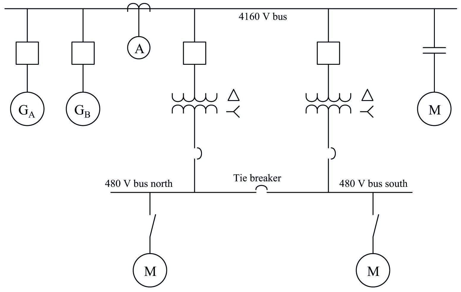
Image Source: Google
The one-line diagram has its greatest application in power flow studies. Electrical elements such as circuit breakers, transformers, capacitors, bus bars, and conductors are shown by standardizing schematic symbols. Instead of representing each of the three phases with a separate line or terminal, only one conductor is represented.
This is in the form of block diagram illustration illustration
The path for power flow between system entities. The elements on the diagram do not represent the physical shape or location of the electrical device, but a general convention is to arrange the diagram with the same left to right, top to bottom sequence
Represented switchgear or other equipment.
A high-line diagram can also be used to show a high-level view of a drain for a PLC control.
system.
The balanced system theory of three-phase power systems tells us that as long as the load on each of the three phases is balanced, we can consider each phase separately. In electrical engineering, this notion is often useful, and for all to consider
The three phases require more effort with very little potential benefit.
An important and often
- The exception is only an odd problem in one or two phases of the system.
- One-line diagrams are commonly used with other notable simplifications, such as per-unit system.
- A secondary advantage of using a one-line diagram is that the simple diagram leaves more
- Location for non-electric, such as economic, information to be included.
In unbalanced systems,
When using the symmetric components method, there are different one-line diagrams.
Each is designed for positive, negative and zero-sequence systems. This simplifies the analysis of unbalanced conditions of a polyphase system.
Electrical equipment for which there are different constraints
Different phase sequences are identified in the diagrams.
For example, a generator would normally have different positive and negative sequences.
Impedance and some transformer winding connections block zero-sequence currents.
The unbalanced system can be solved in three single line diagrams for each sequence and is interconnected to show how unbalanced components add to each part of the system.


No comments:
Post a Comment
Thank you for reading.