Saturday 18 July 2020

Difference between Synchronous Motor and Induction Motor

AC motors are divided into two types, synchronous motors and asynchronous motors also called induction motors. The biggest difference between synchronous and asynchronous motors (induction motors) is whether the speed of the rotor is consistent with the speed of the rotating magnetic field in the stator. If the rotor speed of rotation and the stator field speed are the same, this is called a synchronous motor; otherwise, it is an asynchronous motor. In addition, there are major differences specific to the performance and application parameters between the two.

Difference in construction

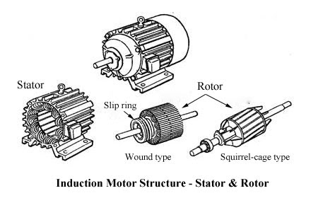
The stator windings of the synchronous and induction motors are similar, and the main difference is in the rotor structure. There are DC field windings in the rotor of the synchronous motor, which must be supplied with the external excitation power introduced through the slip ring. However, the rotor windings of the induction motor are short-circuited, which produce current by electromagnetic induction. On the other hand, synchronous motors are more complex and expensive.

Stator

The components of the synchronous motor stator are basically the same as those of induction motors, playing a role in receiving, producing electrical energy and producing rotating magnetic fields. There is not much difference in the form of the result. The stators of the synchronous motor and the induction motor are made of the magnetic stator core, conductive three-phase AC windings, the base of the fixing core, the terminal cover etc.

Rotor

  • Synchronous motor: the core of the rotor pole is laminated by steel sheets perforated by steel sheets. The pole core is placed by excitation windings that are wound with insulated copper wires. Structure of the PM synchronous motor For permanent magnet synchronous motors, the permanent magnet on the rotor is the key factor to distinguish it from other motors.
  • Induction motor: the rotor consists of iron core and windings, is made of laminated steel sheets and is installed on the rotary shaft. There are two types of rotor: squirrel cage and wound type. The wound type induction motor is also equipped with a slip ring and a brush mechanism.

Difference at work

1. Synchronous motor

The synchronous motor rotates for the interaction between the rotating magnetic field produced by the drive stator windings and the magnetic field generated by the rotor. For the PM synchronous motor, it rotates due to the driving torque generated by the interaction between the rotating magnetic field of the stator and the secondary magnetic field of the rotor. As for the rotor winding, it does not induce current during the normal rotation of the motor and also does not participate in the work. It only serves to start the engine.
During the steady state operation of the synchronous motor, there is a constant relationship between the rotor rotation speed and the grid frequency:
N = Ns = 120f / p
f - the network frequency, p - the number of the motor pole, Ns - synchronous speed.

2. Induction motor

The stator core of the three-phase induction motor is incorporated with symmetrical three-phase windings. After the connection, between the stator and the rotor produces a rotating magnetic field that rotates at a synchronous speed. The rotor bar is cut by the rotating magnetic field in which it produces the induced current. The rotor drive bar is subject to electromagnetic force in the rotating magnetic field, therefore, the rotor overcomes the rotation of the load torque and accelerates its rotation. When the electromagnetic torque is equal to the load torque, the motor rotates at a constant speed.
The rotation speed of the induction motor (stator speed) is slower than the speed of the magnetic field of rotation and this difference is called "slip", expressed by the percentage of synchronous speed:
S = (Ns-N) / Ns.
S - slip, Ns - the speed of the magnetic field, N - the speed of the rotor.

Difference in applications

  • Synchronous motors are used mainly in large generators, while induction motors are almost used as motors to drive machines.
  • For synchronous motors, their power factor can be flexibly adjusted by excitation. However, the power factor of the induction motor is not adjustable; therefore, in some large factories, for the most applied induction motors, a synchronous motor can be added as a phase modifier, to adjust the power factors of the factory and network interface. However, due to the high cost of synchronous motors and a lot of maintenance, capacitors are now commonly used to compensate for the power factor.
  • The operation of the synchronous motor is not as easy as the induction motor because the synchronous motor has the excitation winding and the slip ring in need of a high-level control of the excitation. In addition, compared to the maintenance-free induction motor, the work to keep the motor synchronous is great. So, like an engine, the engine

Construction Of Three Phase Induction Motor

The induction motor, also known as asynchronous motor, is a type of AC electric motor. According to the different power phase, it can be divided into single-phase and three-phase. The main construction of the induction motor consists of two parts - stator and rotor. In addition, there are end bells, bearings, engine structure and other components. Below, more details on the main structure of the three-phase induction motor or the asynchronous motor will be provided.

construction of induction motors


1. Stator
The stator is a fixed part of the induction motor, consisting of an iron core, windings and motor structure.

Stator iron core
As part of the motor's magnetic circuit, it is installed inside the motor frame. It is a hollow cylinder, the outer wall of which is connected to the engine structure. And the stator windings are placed in the groove of the iron core inside. To reduce the loss of the iron core, the iron core of the stator is stacked with 0.5 mm thick silicon steel sheets.
Stator winding
It is a part of the electrical circuit of the motor, generating the rotating magnetic field by inducing three-phase alternating current. The stator windings are wound with insulated copper wires and embedded in the stator slot, which is separated by insulating material between the windings and the slot.
For the methods of connecting the stator windings of the three-phase induction motor, not all of them are connected to the star connection (connection Y). But only under the circumstance of high capacity and high voltage will they connect in this way. In general, as in the low-capacity, low-voltage induction motor, six ends of the three-phase stator winding wire are pulled to connect to the delta connection (Δ connection) or star connection (Y connection). In this way, the motor can be applied to two different levels of supply voltage, for example, the star connection is inserted into the 380V power supply and the delta connection used for the 220V power supply, which can satisfy the need of departure. In other words, it is designed as the delta connection for the 380V power supply and switched to the star connection at startup to achieve the reduced voltage starting objective. Wiring diagram of the three-phase induction motor stator winding
Motor frame
It fixes the stator core and windings and supports the rotor with two bells at the ends. In the meantime, it protects the electromagnet part of the entire engine and dissipates the heat generated during engine operation. The frame is usually made of iron or aluminium.


2. Rotor
The rotor is a rotating part of the induction motor, including iron core, windings and shaft etc.

Rotor iron core
It is also part of the magnetic circuit, usually stacked by silicone steels and fixed to the shaft.
Axis
It plays a role of torque conversion and supports the rotor. It is usually made of medium carbon steel or alloy steel.
Rotor winding
It produces induced current by cutting the magnetic field of the stator and, under the effect of the rotating magnetic field, forces the rotor to rotate. According to the different structure, it can be divided into two types: a squirrel cage rotor and rolled rotor.
The winding rotor windings can be connected to the star or delta connection. In general, the small capacity rotor is connected to the delta while the large and medium capacity rotor is connected to the star. These three ends of the winding wires are connected to three slip rings fixed to the shaft by an electric brush assembly. It can connect the external resistor to the rotor winding circuit. The purpose of rope resistance is to improve the characteristics of the motor or to adjust the speed of rotation.
The structure of the squirrel cage rotor winding is quite different from the structure of the stator. There are slots in the iron core of the rotor with a bar in each slot. Two ends of the iron core that connect all the bars to the external grooves, respectively, form a short circuit. If the iron core is removed from the stator, the shape of the winding is like a squirrel cage. Some bars are made of copper and others are aluminium. If the winding is made of copper, the prepared bare copper bar will be inserted into the crack in the iron core and then covered with copper rings at both ends, followed by welding; if the winding is made of aluminium, the molten aluminium liquid is directly melted into the slits of the iron core of the rotor, melted with rings and fan blades at the same time.

Image Source- Google

Describe the construction of the starters used to start a three-phase slip ring induction motor.

The starting methods of the three-phase induction motor are usually direct online starting, low voltage starting and soft starting.

Direct online match

This type of starting mode is the most basic and simplest when starting the engine. The method is characterized by less investment, simple equipment and a small amount. Although the starting time is short, the torque is lower when starting and the current is large, which is suitable for starting small capacity motors.

Starting with reduced voltage

The reduced voltage starting method can be introduced in medium and large size induction motors to restrict the starting current. When the engine finishes starting, it will run again at full pressure. However, the result of the reduced voltage start will decrease the starting torque. Therefore, the reduced voltage starter is only suitable for starting the motor in unloaded or lightly loaded conditions. Some common methods of starting low voltage are as follows.


Stator circuit series resistance start

A three-phase electrical ballast is inserted into the motor stator winding circuit. The electric ballast can simply be considered as a coil, which can produce induced electromotive force to reduce the direct input power frequency voltage.

Star-delta match

In normal operation, the three-phase induction motor whose stator winding is designed to connect the delta connection can be started in star during the start, to reduce the voltage of each phase of the motor and then reduce the starting current. After finishing the game, he is connected to the delta.
Delta starter is widely used due to its advantages, including simple starter equipment, low cost, more reliable operation and easy maintenance.

Starting the autotransformer

The reduced voltage start of the autotransformer refers that the reduced voltage of the mains energy is connected to the motor stator windings until the speed approaches a constant value and then the motor is connected to the mains.
When starting, the switch is pulled to the "start" position, and the autotransformer is connected to the network, followed by connection to the motor stator windings to obtain a reduced voltage start. When the speed of rotation approaches the nominal value, the key will be pulled to the "operational" position and the motor will directly access the grid under full pressure operation, cutting the autotransformer.

Image Source - Google
Starting the three-phase induction motor autotransformer
The reduced voltage start of the autotransformer is introduced in the star connection for the large capacity motor or normal operation with the start of a certain load. Depending on the load, the transformer tap is chosen according to the required starting voltage and starting torque. At this point, the starting torque is still weakened, but it is not reduced by a third (compared to the reduced voltage start of the star triangle). However, the autotransformer is large and light in size, with the high cost and inconvenient maintenance, which cannot be moved frequently.
Smooth start
The soft starter is a new type control device whose main advantages include soft start, light load and energy-saving and speed. One of the most important features is that the electronic circuit is conducted in the silicon-controlled rectifier of the motor under the tandem connection of the power supply. Using the soft starter to connect the power supply to the motor and different methods to control the driving angle on the silicon-controlled rectifier can cause the motor input voltage to gradually increase from zero and transfer all voltage to the motor from the beginning at the end, what is called a soft start. When starting in this way, the motor torque will gradually increase with the optimized speed. In fact, the soft starter is a voltage regulator that only changes the voltage without changing the frequency at startup.

Friday 17 July 2020

What is a single-phase repulsion motor? Also write several single-phase motor applications?

A motor is an electrical device that converts the electrical input into mechanical output, where the electrical input can be in the form of current or voltage and the mechanical output can be in the form of torque or force. The motor consists of two main parts, namely, the stator and the rotor, where the stator is a stationary part of the motor and the rotor is a rotating part of the motor. A motor that works on the repulsion principle is known as a repulsion motor, where repulsion occurs between two magnetic fields of the stator or rotor. Repulsion motor is a single-phase motor.

What is the repulsion type motor?

Definition: A repulsion motor is a single-phase electric motor that operates by supplying incoming AC (alternating current). The main application of the repulsion engine is electric trains. It starts as a repulsion motor and functions as an induction motor, where the starting torque must be high for the repulsion motor and with very good operating characteristics for the induction motor.

Construction of Repulsion Motor

It is a single-phase AC motor, consisting of a pole core that is the north pole and the south pole of a magnet. The construction of this motor is similar to the split-phase induction motor and the DC series motor. The rotor and the stator are the two main components of the motors that are inductively coupled. The field winding (either a distributed type winding or the stator) is similar to the main winding of the split-phase induction motor. Therefore, the flow is evenly distributed and the space between the stator and the rotor decreases and the reluctance also decreases, which in turn improves the power factor.

The rotor or armature is similar to the DC series motor, which is provided with a drum-type winding connected to the commutator, where the commutator is in turn connected to short-circuit carbon brushes. A brush holder mechanism provides a variable crankshaft to change the direction or alignment of the brushes along the axis. Therefore, the torque produced during this process helps to control speed. The energy in the repulsion motor is transferred by the action of the transformer or by the induction action (where the emf is transferred between the stator and the rotor).

Repulsion Motor Image Source- Google
Principle of work
The repulsion motor works on the principle of repulsion, where two poles of a magnet repel each other. The working principle of the repulsion motor can be explained from 3 cases of α, depending on the position of the magnet as follows.

Case (i): When α = 90 Degrees


Suppose that the 'C and D' brushes are aligned vertically at 90 degrees and the rotor is horizontally aligned along the d axis (field axis), which is the direction of the current flow. From the principle of Lenz's law, we know that the induced emf depends mainly on the flow of the stator and the current direction (which is based on the alignment of the brushes). Therefore, the net emf resulting from the brush from 'C to D' is '0', as shown in the diagram, which is represented as 'x' and '.', There is no current flow in the rotor, therefore Ir = 0. When no current passes through the rotor, so it acts as an open circuit transformer. Therefore, the stator current is = less. The direction of the magnetic field is in the direction of the brush axis, where the axis of the stator and rotor field has a 180-degree phase shift, the torque generated is '0' and the mutual induction induced in the motor is '0'.

Case (ii): When α = 0


The 'C and D' brushes are now oriented along the d axis and are short-circuited. Therefore, the net emf induced in the motor is very high, which generates the flow between the windings. The liquid emf can be represented as 'x' and '.', As shown in the figure. It is similar to a short-circuit transformer. Where the stator current and mutual induction are maximum, which means Ir = Is = maximum. From the figure, we can see that the fields of the stator and rotor are 180 degrees opposite in phase, which means that the generated torque will oppose so that the rotor cannot rotate.
Case (iii): When α = 45 When brushes 'C and D' are tilted at some angle (45 degrees) and the brushes are shorted. Let's assume that the rotor (brush axis) is fixed and the stator is rotated. The stator winding is represented as the number of 'Ns' of effective turns and the current passage is 'Is', the field produced by the stator is in the 'Is Ns' direction, which is the MMF of the stator, as shown in the figure. The MMF (magnetomotive force) is solved in two components (MMF1 and MMF2), where MMF1 is together with the brush direction (Is Nf) and MMF2 is perpendicular to the brush direction (Is Nt), which is the direction of the transformer, and 'α' is the angle between 'Is Nt' and 'Is Nf'. Therefore, the flow produced by this field in two components is 'Is Nf' and 'Is Nt'. The rotor-induced emf produces flow along the q axis.

The field produced by the rotor along the brush axis is mathematically represented as follows 
 É Nt = É Ns cos α ……… .. 1 
 Nt = Ns Cos α ………… 2 
 Nf = Ns Sin α ………… 3 

Repulsion Engine Classification 


There are three types of repulsion engines: Plywood Type It consists of an additional winding, that is, a compensation winding and an additional pair of brushes are placed between the brushes (short-circuited). The compensation winding and a pair of brushes are connected in series to improve the power and speed factors. A compensated type motor is used where high power is needed at the same speed. Compensated type repulsion motor offset type repulsion engine Induction type of onset of repulsion It starts with the coil repulsion and runs with the induction principle, where the speed is kept constant. It has a single stator and rotor similar to the DC armature and a switch, in which a centrifuge mechanism causes a short circuit in the switch bars and has higher torque (6 times) than the current in the load. The repulsion operation can be understood from the graph, that is, when the frequency of the synchronous speed increases, the percentage of the total torque load begins to decrease, where at one point the magnet poles experience a repulsive force and pass to the induction mode. Here we can see the load that is inversely proportional to the speed. Repulsion-Start-Induction-Motor Chart repulsion-start-induction-motor-graphic Repulsion type It works with the principle of repulsion and induction, which consists of a stator winding, 2 winding rotors (where one is a squirrel cage and the other is a direct current winding). These windings are shorted for the commutator and two brushes. Operates in a condition where the load can be adjustable and whose initial torque is 2.5  to 3. 

Repulsion type like repulsion Benefits 

The advantages are The high value of the initial torque Speed ​​is not limited By adjusting the value of 'α', we can adjust the torque, where we can increase the speed based on the torque adjustment. By adjusting the position brushes, we can control torque and speed easily. 


Disadvantages 

The disadvantages are Speed ​​varies with load variation The power factor is less, except at high speeds The cost is high High maintenance. 

Forms Applications are They are used where starting torque is required with high-speed equipment Coil reels: where we can adjust the speed flexibly and easily and the direction can also be changed by reversing the direction of the brush axis. 
1. Toys 
2. Elevators, etc. 
Since the magnetic axis 'T' and the brush axis coincide with the MMF rotor that is along the brush axis it is equal to the flow generated by the stator.

All about transformer oil or transformer insulating oil

Transformer oil is used in the oil-filled transformer and in some other system, such as high voltage capacitors, fluorescent lamp reactors, circuit breakers, etc.


The basic requirement of transformer oil is that it must be stable at high temperatures, with excellent electrical insulation properties and adequate cooling properties.

The standard for transformer oil


  • ASTM D3487 - 09 is the standard specification for mineral insulating oil used in electrical appliances. ASTM - American Society of Tests and Materials.


How transformer oil is used in the liquid type transformer

The core and windings of the liquid-cooled power transformer are submerged with transformer oil.


Transformer oil function

Following are the function of the transformer oil


  • As a means of electrical insulation
  • As a cooling medium (transfer the heat to the tank/conservator wall).
  • Arc and crown suppression.

Phasor Diagram Of Synchronous Generator

In this article, we will discuss one of the easiest methods of making the phasor diagram for a synchronous generator. Now, let's write the various notes for each quantity in a single location, this will help us understand the phasor diagram more clearly. In this phasor diagram, we will use:

Ef, which indicates excitation voltage

Vt indicating terminal voltage

Ia that denotes the chain of the armature

θ that denotes the phase angle between Vt and Ia

ᴪ that denotes the angle between Ef and Ia

δ that denotes the angle between Ef and Vt

which indicates the strength of the reinforcement per phase

To draw the phasor diagram, we will use Vt as a reference. Consider these two important points that are written below:


  • We already know that if a machine is working as a synchronous generator, the direction of Ia will be in phase with that of Ef.
  • Phasor Ef is always ahead of Vt.

These two points are necessary to make the phasor diagram of the synchronous generator. Given below is the phasor diagram of the synchronous generator:

In this phasor diagram, we trace the direction of Ia in phase with that of Ef, as per point 1 mentioned above. Now we are going to derive an expression for the emf excitation in each case. We have three cases written below:


  1. Generating operation with delayed power factor.
  2. Generation operation on the unit's power factor.
  3. Generation operation on the main power factor.

The following are the phasor diagrams for all operations.

Image Source- Google

Synchronous Motor Excitation System

Before understanding this excitation of the electrical motor, it must be remembered that any electromagnetic device must draw a magnetizing current from the AC source to supply the required workflow. This magnetizing current is nearly 90o at the supply voltage. In other words, the function of this magnetizing current or delayed VA attracted by the electromagnetic device is to align the flow within the magnetic circuit of the device. So it comes under an electromagnetic device. It receives three-phase electrical supply to the armature winding and DC power to the rotor winding.

Synchronous motor excitation refers to the DC power supplied to the rotor, which is employed to provide the required magnetic flux.

One of the most and unique characteristics of this motor is that it's frequently operated on any electric power factor that drives, is delayed or with a unit, and this feature is predicated on the excitation of the electrical motor. When the electric motor is running at constant applied voltage V, the resulting air gap flow, as needed by V, remains substantially constant. This resulting air gap is established by the cooperation of the AC supply of the armature winding and therefore the DC supply of the rotor winding.

Synchronous motor excitation refers to the DC power supplied to the rotor, which is employed to supply the required magnetic flux.

One of the most and unique characteristics of this motor is that it is often operated on any electric power factor it's carrying, with delay or unit, and this feature is predicated on the excitation of the electric motor. When the electric motor is working with constant applied voltage V, the resulting air gap flow, as needed by V, remains substantially constant. This resulting air gap is established by the cooperation of the AC supply of the armature winding and therefore the DC supply of the rotor winding.

CASE 1: When the sector current is sufficient to supply the air gap flow, as needed by the constant supply voltage V, the magnetization current or the delayed reactive VA required from the AC source is zero and therefore the motor operates with the factor the unit's power. the sector current, which causes this unit power factor, is named normal excitation or normal field current.


CASE 2: If the sector currently isn't sufficient to supply the required air gap flow, as needed by V, the extra magnetization current or delayed reactive VA are going to be drawn from the AC source. This magnetizing current produces the deficient flow (constant flow configured by the winding of the DC supply rotor). Therefore, during this case, the engine is claimed to work under a delayed power factor and is claimed to be under excitation.

CASE 3: If the sector current is bigger than the traditional current, the motor is excited. This excess current within the field produces excess flow (flow configured by the winding of the DC supply rotor - flow resulting from the air gap) that has got to be neutralized by the armature winding.

Therefore, the armature winding absorbs the most reactive VA or the initial voltage of the demagnetizing current at almost 90o from the AC source. Therefore, during this case, the engine operates under the most power factor.

This whole concept of excitation and power factor of the electric motor is often summarized within the following graph. this is often called the V curve of the electric motor.


Image Source- Google

Conclusion: An overexcited electric motor operates with the main power factor, an under excited electric motor operates with a lagged power factor and a traditional excited electric motor operates with one power factor.

Armature reaction in the alternator or synchronous generator

Every rotating electrical machine works based on Faraday's law. Every electrical machine requires a magnetic field and a coil (known as armature) with relative movement between them. In the case of an alternator, we supply electricity to the pole to produce a magnetic field and the output energy is removed from the armature. Due to the relative movement between the field and the armature, the armature conductor cuts off the flow of the magnetic field and, therefore, there would be changes in the flow connection with these armature conductors. According to Faraday's law of electromagnetic induction, there would be an induced emf in the armature. Thus, as soon as the load is connected to the armature terminals, there is a current flowing in the armature coil.

As soon as the current begins to flow through the armature conductor, there is a reverse effect of this current on the flow of the alternator's main field (or synchronous generator). This reverse effect is called an armature reaction in the alternator or synchronous generator. In other words, the effect of the armature flow (stator) on the flow produced by the poles in the rotor field is called the armature reaction.

We already know that a current conductor produces its own magnetic field, and that magnetic field affects the alternator's main magnetic field.

It has two undesirable effects: it distorts the main field or reduces the flow of the main field or both. They deteriorate the performance of the machine. When the field is distorted, it is known as a cross magnetization effect. And when the field flow is reduced, it is known as a demagnetizing effect.

The conversion of electromechanical energy takes place through the magnetic field as a medium. Due to the relative movement between the armature conductors and the main field, an emf is induced in the armature windings whose magnitude depends on the relative speed and magnetic flux. Due to the reaction of the armature, the flow is reduced or distorted, the induced net fraction is also affected and, therefore, the performance of the machine decreases.

Alternator armature reaction
In an alternator like all other synchronous machines, the effect of the armature reaction depends on the power factor, that is, the phase relationship between the terminal voltage and the armature current.

Reactive power (delay) is the energy of the magnetic field; therefore, if the generator supplies a delayed load, it implies that it is supplying the load with magnetic energy. As this energy comes from the excitation of the synchronous machine, the net reactive energy is reduced in the generator.

Therefore, the reaction of the armature is demagnetizing. Likewise, the armature reaction has a magnetizing effect when the generator supplies an initial charge (as the main charge carries the main VAR) and, in return, supplies delayed VAR (magnetic energy) to the generator. In the case of a purely resistive load, the armature reaction is only cross-magnetized.

The reaction of the alternator armature or synchronous generator depends on the phase angle between the stator armature current and the voltage induced in the alternator armature winding.

The phase difference between these two quantities, that is, current and voltage of the armature, can vary from - 90o to + 90o

If that angle is θ, then


 To understand the real effect of this angle on the alternator armature reaction, we’ll consider three standard cases,

When θ = 0
When θ = 90o
When θ = - 90o

The reaction of alternator armature in unit power factor
In the power factor of the unit, the angle between the armature current I and the induced emf E is zero. This means that the armature current and the induced emf are in the same phase. But we know theoretically that the EMF induced in the armature is due to the change in the flow of the main field, connected to the armature conductor.

As the field is excited by DC, the main flow of the field is constant with the field magnets, but it would be alternated with the armature, as there is a relative movement between the field and the armature in the alternator. If the flow of the alternator's main field with the armature can be represented as


Then the induced emf through the armature is proportional to dɸf / dt.


Therefore, from these equations (1) and (2) above, it is clear that the angle between, φf and the induced emf will be 90o.

Now, the armature flow φa is proportional to the armature current I. Therefore, the armature flow is in phase with the armature current I.

Again, in the unit, the electric power factors I and E are in the same phase. Therefore, in the power factor of the unit, is in phase with E. Therefore, in this condition, the armature flow is in phase with the induced EMF and the field flow is in quadrature with E. Therefore, the armature flow φa is square to the main field flow φf.

As these two flows are perpendicular to each other, the reaction of the alternator armature in the power factor of the unit is of the type of distortion or cross magnetization.

As the armature flow pushes the main field flow perpendicularly, the main field flow distribution under one face of the pole does not remain uniformly distributed. The density of the flow under the tips of the poles on the right increases slightly, while under the tips of the poles in front it decreases.

Alternator armature reaction in delayed zero power factor
At the zero delay power factor, the armature current is 90o for the emulsion induced in the armature.

Like the emf induced in the armature coil due to the main field flow, the emf takes the main field flow by 90o. From equation (1) we obtain the field flow,


Therefore, at ωt = 0, E is maximum and φf is zero.

At ωt = 90o, E is zero and φf has the maximum value.

At ωt = 180o, E is maximum and φf zero.

At ωt = 270o, E is zero and φf has a maximum negative value.

Here, got the maximum value 90 ° before E. Therefore leads E by 90 °.

Now, the armature current I is proportional to the armature flow φa and I is E at 90o. Therefore, is E at 90o.

Thus, it can be concluded that the flux of field flow takes E at 90o.

Therefore, the armature flow and the field flow act directly opposite to each other. Thus, the alternator armature reaction in the zero delay power factor is a purely demagnetizing type. This means that the flow of the armature directly weakens the flow of the main field.

The reaction of alternator armature in the main power factor
In the condition of the main power factor, the armature current "I" induces the fem E by an angle of 90o. Again, we show only the derived leads field flow, induced by EME by 90o.

Again, the armature flow φa is proportional to the armature current I. Therefore, φa is in phase with I. Therefore, the armature flow φa also takes E, at 90o, as I conduct E, at 90o.

As in this case, both the flux of the armature and the lead of the flux of the field, induced by the fem E by 90o, it can be said that the flux of the field and the flux of the armature are in the same direction. Therefore, the resulting flow is simply the arithmetic sum of the field flow and the armature flow. Therefore, finally, it can be said that the alternator armature reaction due to a purely main electrical power factor is the type of magnetization.

Nature of the armature reaction


  1. The reaction flow of the armature is constant in magnitude and rotates at synchronous speed.
  2. The armature reaction is cross-magnetized when the generator provides a load on the unit's power factor.
  3. When the generator provides a load on the main power factor, the armature reaction is partially demagnetized and partially crossed magnetized.
  4. When the generator provides a load on the main power factor, the armature reaction is partially magnetized and partially crossed magnetized.
  5. The armature flow acts independently of the main field flow.
Image Source- Google

Parallel operation of synchronous generator

The Alternator is really an AC generator. In the alternator, an EMF is induced in the stator (fixed wire) by the effect of the rotating magnetic field (rotor) due to Faraday's law of induction. Due to the modern rotational speed of the field poles, it is also known as the modern generator.

Here, we can discuss the parallel operation of the synchronous generator. When AC systems are interconnected for efficiency, the alternators must also be connected in parallel. There will be more than two synchronous generators connected in parallel to the production stations.

Condition for parallel application of the synchronous generator

Search for comments that I need to complete for parallel use of the converter. Before applying, you should look for the additional information required as.


  1. The method of providing screen access, display and zoom and infinite channel line beauty is also known as synchronization.
  2. Running machines are the machine that changes the load.
  3. The incoming machine is the exchanger or machine that you need to list delivery with the system.


The conditions that must be met are

1. The phase sequence of the input motor voltage and the busbar voltage must be the same.
2. The RMS (terminal voltage) line voltage of the busbar or the current machine and the incoming machine must be the same.
3. The phase angle of the two systems must be equal.
4. The frequency of the two terminals (input motor and busbar) must be almost the same. Large transient currents will occur when the frequencies are not nearly the same.

Departure from the above conditions will result in the formation of surges and current. It also leads to unwanted electromechanical oscillation of the rotor which leads to equipment damage.

General procedure for parallel synchronous generator

The following figure shows an alternator (generator 2) paralleling a power system (generator 1). These two machines are to be synchronized to supply power to a load. Generator 2 is almost parallel with the help of a switch, S1. This switch must never be closed without fulfilling the above conditions.

Image Source- Google

  1. To be equal to the voltages of the terminals. This can be done by adjusting the voltage at the input machine terminal by changing the field current and making it equal to the operating system line voltage using voltmeters.
  2. There are two methods for controlling the phase sequence of machines. They are as follows


  • The first uses a Synchroscope. It does not actually control the phase sequence but is used to measure the difference in phase angles.
  • The second method is the three lamp method (Figure 2). Here we can see three lamps connected to the switch terminals, S1. The lamps are bright if the phase difference is large. The lamps dim if the phase difference is small. The lamps will appear dim and bright together if the phase sequence is the same. The lamps will be bright in progress if the phase sequence is opposite. This sequence of phases can be matched by changing the connections in two phases on one of the generators.

Image Source- Google
3. Next, we have to check and verify the frequency of the system received and running. It must be almost the same. This can be done by inspecting the frequency of dimming and brightness of the lamps.
4. When the frequencies are almost equal, the two voltages (input alternator and operating system) change the phase gradually. These changes can be observed and switch S1 can be closed when the phase angles are equal.

Advantages of parallel synchronous generator
  • When maintenance or inspection occurs, one machine can be taken out of service and the other alternators can maintain continuity of supply.
  • The cargo supply can be increased.
  • During light loads, more than one alternator can be switched off while the other operates at an almost full charge.
  • High efficiency.
  • The operating cost is reduced.
  • It guarantees the protection of the supply and allows an economical generation.
  • The generation cost is reduced.
  • The failure of a generator does not cause any interruption in the supply.
  • The reliability of the entire power system increases.

Tuesday 4 February 2020

EMF equation of DC generator


As the armature turns, a voltage is created in its loops. On account of a generator, the emf of the pivot is known as the Generated emf or Armature emf and is indicated as Er = Eg. On account of an engine, the emf of the pivot is known as Back emf or Counter emf and spoke to as Er = Eb. The articulation for emf is same for both the tasks. I.e., for Generator just as for Motor.
Derivation of EMF Equation of a DC Machine – Generator and Motor
Let,
  • P – Number of poles of the machine
  • ϕ – Flux per pole in Weber.
  • Z – Total number of armature conductors.
  • N – Speed of armature in revolution per minute (r.p.m).
  • A – number of parallel paths in the armature winding.
In one revolution of the armature, the flux cut by one conductor is given as
EMF-EQUATION-OF-DC-GENERATOR-EQ1
Time taken to complete one revolution is given as
EMF-EQUATION-OF-DC-GENERATOR-EQ2
Therefore, the average induced e.m.f in one conductor will be
EMF-EQUATION-OF-DC-GENERATOR-EQ3
Putting the value of (t) from Equation (2) in the equation (3) we will get
EMF-EQUATION-OF-DC-GENERATOR-EQ4
The number of conductors connected in series in each parallel path = Z/A.
Therefore, the average induced e.m.f across each parallel path or the armature terminals is given by the equation shown below.
EMF-EQUATION-OF-DC-GENERATOR-EQ5
Where n is the speed in revolution per second (r.p.s) and given as
EMF-EQUATION-OF-DC-GENERATOR-EQ6
For a given machine, the number of poles and the number of conductors per parallel path (Z/A) are constant. Hence, equation (5) can be written as
EMF-EQUATION-OF-DC-GENERATOR-EQ7
Where, K is a constant and given as
EMF-EQUATION-OF-DC-GENERATOR-EQ8
Therefore, the average induced emf equation can also be written as
EMF-EQUATION-OF-DC-GENERATOR-EQ9
Where K1 is another constant and hence induced emf equation can be written as
EMF-EQUATION-OF-DC-GENERATOR-EQ10
Where ω is the angular velocity in radians/second is represented as
EMF-EQUATION-OF-DC-GENERATOR-EQ11
Along these lines, plainly the instigated emf is straightforwardly relative to the speed and motion per shaft. The extremity of instigated emf relies on the bearing of the attractive field and the heading of revolution. If both of the two is turn around the extremity changes, however, if two are switched the extremity stays unaltered. 

This initiated emf is an essential wonder for all the DC Machines whether they are filling in as a generator or engine. 

If the machine DC Machine is filling in as a Generator, the instigated emf is given by the condition demonstrated as follows.
EMF-EQUATION-OF-DC-GENERATOR-EQ12
Where Eis the Generated Emf
If the machine DC Machine is working as a Motor, the induced emf is given by the equation shown below.
EMF-EQUATION-OF-DC-GENERATOR-EQ13
In a motor, the induced emf is called Back Emf (Eb) because it acts opposite to the supply voltage.

Why Alternator/Generator Rated in kVA. Not in kW?

As we definitely realize that why transformer evaluated in kVA rather than kW, the same reason here, for example, the power √3 VL IL Cos θ c...