EMF Equation of an Alternator/AC Generator
An alternator or AC generator (dynamo) is a gadget which converts mechanical Vitality to electrical vitality. When we supply the charging current by DC shunt generator through two slip rings (in ongoing alternators, they utilize electronic beginning framework rather than slip rings and commutators) because the field magnets are pivoting. remember that most alternators utilize a pivoting attractive field with a stationary armature.
At the point when the rotor turns, the stator conductors which are static in the event of alternator cut by attractive motion, they have instigated EMF delivered in them (as per Faraday's law of electromagnetic enlistment which expresses that if a conductor or loop joins with any evolving transition, there must be a prompted emf in it.
Note: We will examine the development, Working and Operation. Sorts of Alternators in subtleties in our next posts.EMF Equation of an Alternator and AC Generator
This incited EMF can be found by the EMF condition of the alternator which as pursues:
Lets,
P = No. of shafts
Z = No. of Conductors or Coil sides in arrangement/stage, for example, Z = 2T… Where T is the number of loops or turns per stage (Note that one turn or curl has two finishes or sides)
f = recurrence of actuated EMF in Hz
Φ = Flux per shaft (Weber)
N = rotor speed (RPM)
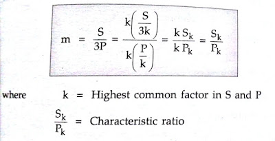
Kd= Distribution factor = Kd= Distribution factor for emf condition of alternator and air conditioning generator
Where Distribution factor = Kd =distribution factor
Kc or KP = Cos α/2
Whenever initiated EMF is accepted sinusoidal at that point,
Kf = Form factor = 1.11
In one upheaval of the rotor for example in 60/N seconds, every conductor is cut by a transition of ΦP Webers.
dφ = ΦP and furthermore dφ = 60/N seconds
at that point incited e.m.f per conductor ( normal) = EMF EQUATION OF AN ALTERNATOR OR AC GENERATOR… .. (I)
In any case, we realize that:
f = PN/120 or N= 120f/P
Putting the estimation of N in Equation (I), we get,
Normal estimation of EMF per conductor = EMF EQUATION OF AN ALTERNATOR∴ (N= 120f/P)
On the off chance that there are Z conductors in arrangement per stage,
at that point normal e.m.f per stage = 2 f Φ Z Volts = 4 f ΦT Volts … .. (Z=2T)
Likewise, we realize that;
Structure Factor= RMS Value/Average Value
= RMS value= Form factor x Average Value,
= 1.11 x 4fΦT = 4.44fΦT Volts.
(Note that is the very same condition as the EMF condition of the transformer)
What's more, the real accessible voltage per stage
= 4 Kc Kd f ΦT = 4 Kf Kc Kd f ΦT Volts.
Note: If alternator or AC generator is star associated as ordinarily the case, at that point the Line Voltage is √3 times the stage voltage as got from the above recipe


